April 27, 2025
With a tight project schedule, the manufacturer delivered on time, and on-site technical personnel provided guidance throughout the entire installation and commissioning process; the collaboration was highly efficient and hassle-free.
Sep 19, 2026
A step-up transformer bridges the voltage gap between a Battery Energy Storage System (BESS) and the utility grid. Most BESS inverters output AC voltage in the range of 400V to 690V, while grid interconnection typically demands 11kV, 33kV, or higher. The step-up transformer elevates this low-voltage output to a transmission-compatible level, reducing I²R losses during energy transfer and enabling stable, code-compliant grid injection. Without this voltage conversion stage, efficient BESS grid integration is technically unachievable at commercial scale.
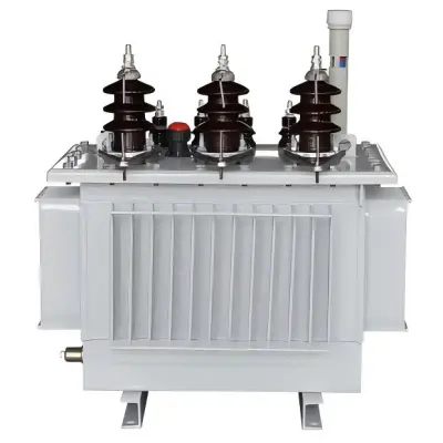
A step-up transformer has a secondary winding with more turns than the main winding. This is because of Faraday's Law of Electromagnetic Induction. This turns ratio (k > 1) raises the output voltage while lowering the current. In a BESS setup, the transformer gets low-voltage AC from the inverter block and sends high voltage that works with the grid to the secondary terminals. Grain-oriented silicon steel (CRGO) is often used in core building to reduce hysteresis and eddy current losses. This makes the whole storage system more efficient round-trip.
Picking the correct voltage-boosting transformer for a BESS project has clear operational advantages. What makes this technology so important are these main benefits:
There is less loss because the wire cross-sections are better and the CRGO cores are more efficient. This keeps no-load losses below the levels needed by U.S. Department of Energy efficiency guidelines.
Picking the right transformer carefully protects both the storage asset and the deal to connect to the grid. There are two problems that always come up on real projects.
The charge-discharge cycles of the BESS cause the DC bus voltages to change, which causes the inverter's AC output to change too. This variation is fixed by on-load tap changers (OLTC) or electrically controlled tap positions, which keep the secondary voltage within ±2% of the standard grid voltage. If there isn't enough voltage regulation, the point of common coupling (PCC) could see voltage changes that cause it to automatically disconnect according to the rules in FERC Order 2222.
To make sure that a transformer works well for 25 to 30 years, it needs to be carefully set up and serviced on a regular basis. An annual Dissolved Gas Analysis (DGA) of oil-immersed units can find early signs of insulation breakdown before it gets so bad that it breaks. Regular Hi-pot dielectric testing confirms the integrity of the insulation. Type and regular tests, such as short-circuit withstand, temperature rise, and impulse testing, must be done in accordance with both IEC 60076 and IEEE C57.12.00 before any unit leaves the plant. Every delivery should come with a factory acceptance test (FAT) record, which should be checked by the procurement team.
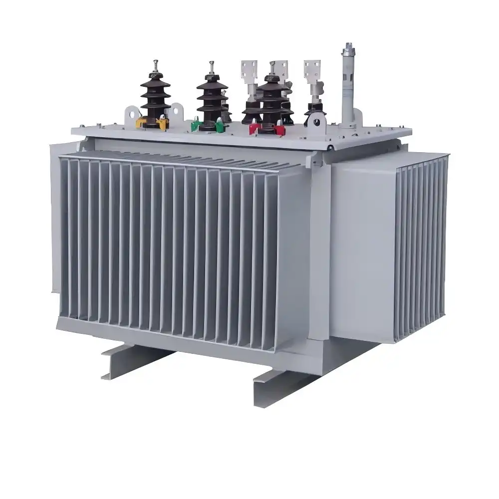
Not every voltage regulator works well with BESS grid connections. The following comparison looks at the four options that electrical experts and EPC companies most often look at.
Before agreeing on an answer, it's important to understand these differences:
For BESS projects over 500 kW, a dedicated step-up transformer with OLTC capability is still the best and most widely proven option. It provides galvanic isolation, high MVA capacity, and voltage control all in one low-maintenance unit.
Engineers should be very clear about the following when they send out an RFQ: the primary voltage (BESS inverter output), the secondary voltage (grid interconnection voltage), the MVA rating with a 20% overload margin, the impedance percentage (usually 5–6% for BESS applications), the vector group (Dyn11 is standard for three-phase grid tie), the cooling method (ONAN or ONAF), and the harmonic K-factor rating to deal with distortion caused by the inverter.
When purchasing managers look at a step-up transformer provider, they should look at four business factors in addition to technical ones. Coverage of certificates is very important. ISO 9001:2015, IEC 60076, CE, and UL certifications show that the maker follows a quality system that can be checked. For utility-scale projects with phased energization schedules, lead time and the ability to supply in batches are very important. Customization responsiveness, especially for non-standard voltage ratios that are common in North American BESS projects, is what sets capable manufacturers apart from suppliers who only sell from catalogs. Support after delivery, such as help with commissioning and the availability of spare parts, has a direct effect on project uptime.
Fast progress is being made in smart transformer technology. IoT-enabled condition monitoring builds thermal sensors, partial discharge detectors, and DGA monitors into the transformer itself. These sensors send real-time information about the transformer's health to SCADA systems. This change from time-based to condition-based maintenance cuts down on unexpected outages and improves the cost-effectiveness of asset lifecycle management, which is important for utility-scale BESS owners who are in charge of multiple sites.
Amorphous alloy cores are being used in BESS step-up designs. They have already been used successfully in distribution transformers. Amorphous cores cut no-load losses by about 70% compared to CRGO silicon steel, which makes the system's round-trip efficiency much better. As the percentage of renewable energy in the U.S. grid gets closer to the 30–35% range that the DOE predicts for 2030, low-loss transformer designs will have a bigger impact on project IRR estimates.
Community microgrids and decentralized grid designs are also making the range of uses bigger. BESS-integrated microgrids need step-up units with ratings ranging from 500 kVA to 50 MVA. This covers a wide range of project sizes and forces makers to make modular, pre-tested transformer systems that can work with substations that have already been built.
A correctly chosen step-up transformer is the hidden key to every BESS grid connection project that makes money. It changes the voltage from the inverter to a level that can work with the grid, protects against galvanic current, handles harmonic loads, and keeps working properly for decades. As the use of energy storage grows across the US, the quality and technical detail of the generator solution directly affects how well a project meets its performance goals. It is not an extra choice to find a manufacturer with proven design skills, certified quality processes, and quick response times for customization; it is essential for the project's financial success.
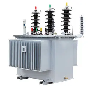
Most utility-scale BESS installations use voltage ratios stepping up from 400V–690V (inverter output) to 11kV, 33kV, or 34.5kV (U.S. distribution grid standard). The exact ratio depends on the interconnection agreement with the local utility.
Yes. Units specified with an appropriate harmonic K-factor and Class F or H insulation are designed for the non-sinusoidal current waveforms produced by BESS inverters during rapid cycling.
Annual DGA testing is recommended for oil-immersed units in BESS service. Dielectric strength (BDV) tests and visual inspections should occur every 12–24 months depending on load cycling intensity.
With correct specification and preventive maintenance, well-engineered units deliver a 25–30 year service life, aligned with typical BESS project financing horizons.
Most U.S. utility interconnection standards and IEEE 1547-2018 require galvanic isolation between the BESS and the grid, making a dedicated step-up transformer with separate primary and secondary windings the compliant solution.
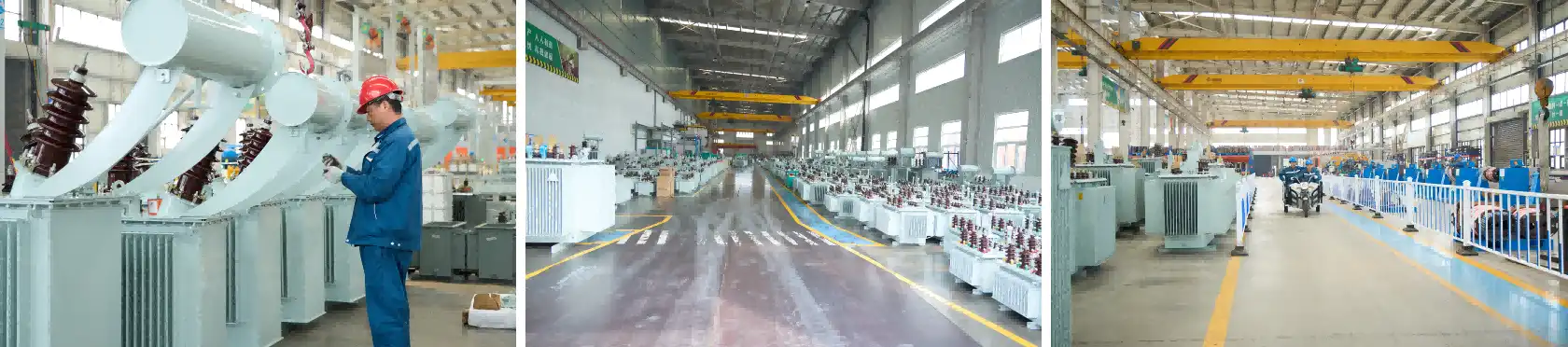
Lijie Electric Power Technology Group engineers and manufactures a complete range of step-up transformers from 35kV to 500kV, certified to ISO 9001:2015, IEC 60076, CE, and UL standards. With over 2,000 employees, 500,000 m² of production capacity, and annual sales exceeding 5 billion RMB, we are a step-up transformer manufacturer capable of supporting large-volume BESS projects with custom designs and reliable delivery. Contact our technical team today at lijieelectrical@gmail.com or visit lijie-electrical.com to request a tailored quotation.
1. IEEE Standard C57.12.00 – IEEE Standard for General Requirements for Liquid-Immersed Distribution, Power, and Regulating Transformers, IEEE, 2021.
2. IEC 60076-1 – Power Transformers – Part 1: General, International Electrotechnical Commission, 2011.
3. U.S. Department of Energy – Energy Storage Grand Challenge Roadmap, DOE, 2020.
4. FERC Order 2222 – Participation of Distributed Energy Resource Aggregations in Markets Operated by Regional Transmission Organizations, Federal Energy Regulatory Commission, 2020.
5. IEEE 1547-2018 – Standard for Interconnection and Interoperability of Distributed Energy Resources with Associated Electric Power Systems Interfaces, IEEE, 2018.
6. National Renewable Energy Laboratory (NREL) – Grid-Scale Battery Storage: Frequently Asked Questions, NREL Technical Report, 2019.
YOU MAY LIKE




12%20type%20epoxy%20resin%20cast%20transformer.webp)

April 27, 2025
With a tight project schedule, the manufacturer delivered on time, and on-site technical personnel provided guidance throughout the entire installation and commissioning process; the collaboration was highly efficient and hassle-free.
July 2, 2025
During the preliminary phase, a selection plan was custom-tailored based on the actual site load requirements, resulting in a high degree of parameter compatibility. After-sales support responds within two hours, and ongoing technical support for operation and maintenance is comprehensive; we feel completely confident in a long-term partnership.
November 18, 2025
Deployed as a supporting component for a 35kV grid-connection project at a photovoltaic power station, the equipment operates for an average of 16 hours daily. It demonstrates excellent control over no-load losses, ensures smooth power generation and grid integration, and effectively reduces the station's overall energy consumption.
January 30, 2026
Under the continuous, high-load operating conditions of a factory production line, the equipment maintains stable electrical parameters and exhibits strong overload resistance, thereby guaranteeing an uninterrupted power supply for industrial production.
April 3, 2026
Integrated as a supporting component for a new energy photovoltaic grid-connection system, the manufacturer provided professional technical coordination and timely after-sales support, ensuring seamless adaptation to the specific electrical operating conditions required for grid integration.